Typical Operating Conditions for AC Gearmotors and Motors

Definition of Gearmotor Output Torque Rating
For standard gearmotors, the torque rating shown on the product nameplate (or in the manufacturer’s sales literature) represents a complete gearmotor rating and reflects the capacity of the limiting gearmotor design elements. Some of the design limitations considered are: motor input power, strength or wear rating of the gearing, radial and thrust capacity of the bearings, and strength of the gear shafts and output shaft (drive shaft). Gearmotor torque ratings should not be exceeded at continuous duty operation.
Nameplate values stipulate the limits at which a motor or gearmotor can safely operate. To operate the motor either over or under the nameplate rated limit can have adverse effects on motor performance and safety. Some of the restrictions and associated consequences of ignoring them are listed below.

AC Gearmotor and Motor User Guidelines:
Operating Frequency
Do not operate AC induction motors at voltages beyond ± 10% of nameplate rating. Higher voltages produce adverse effects on motor temperature, noise and vibration, operation of current-sensitive relays, motor life and capacitor life, and could create nuisance operation of thermal overload protectors. Voltages below 10% create starting problems with current-sensitive starting relays and could cause thermal overload protectors, with internal heating coils, to trip at winding temperatures which exceed the maximum allowable limits.
Do not operate AC induction motors from a nominal power source frequency other than that specified on the nameplate. With the exception of brush-type motors, AC motor speed varies directly with frequency. While it is understandable that some OEM machines are designed to operate at more than one line frequency, e.g. US equipment exported to Europe, any decrease in speed due to reducing the frequency may have an adverse effect on temperature and on the proper operation of centrifugal cutout switches (split phase motors) and relays. At increased frequencies, the torque capability is reduced, and starting relays may fail to engage the auxiliary winding.


AC motor laminations (and the windings installed in them) are specifically designed for operation at nameplate frequencies. For example, the laminations for 60 Hz motors are considerably different than those used for 400 Hz motors. In addition, manufacturers of AC motors usually don’t performance-test their fixed-speed AC motors at frequencies other than the nameplate frequency rating. Since the amount and type of noise and vibration emanating from a motor will change directly with frequency, undesirable hum and other resonance effects are quite likely with deviations from nameplate frequencies.
Dual frequency (50/60 Hz) AC motors can be provided by most gearmotor manufacturers, usually at output ratings lower than the standard 60Hz rating for a given frame size.
Nameplate Torque Ratings
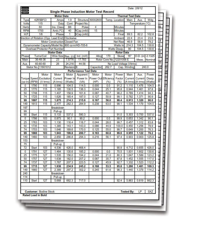
Do not operate any AC gearmotor or motor at torques in excess of nameplate rating. The rated torque can be calculated from the desired operating speed, torque and motor power (in Watts or Horsepower). Overload limitations also apply to gearmotors where maximum gearhead torque is shown. Technical assistance should be requested from the manufacturer if overloads are anticipated. Operation at higher torque loads can result in lower speeds, higher winding temperatures, reduced life of windings, gears and bearings, and nuisance operation of thermal overload protectors. In many cases, overloads can create hazards to personnel. Noise and vibration also increase with excessive loading.
PSC Gearmotors or Motors at Light Loads
 We recommend to not operate permanent split capacitor (PSC) gearmotors or motors at light loads. An inherent characteristic of permanent split capacitor AC induction motors is they generally operate at elevated temperatures when lightly loaded. To prevent PSC motors from running “too hot”, they should be matched to the application with respect to their load.
Common Motor Formulas
Motor Torque for a given horsepower Rating and Speed
| T [oz-in] | = | HP x 63025 x 16 |
| N (rpm) |
Gearmotor Torque (out) with known motor torque
| T [lb-in] | = | (Tm - SF) [oz-in] | x | R x Eff |
| 16 |
| Tm | = Motor Torque |
| SF | = Seal Friction |
| R | = Ratio |
| Eff | = Efficiency |

Ambient Temperature Rating
Do not exceed the geared motor’s nameplate ambient temperature rating. Lack of air intake, obstructions to the ventilation flow, and major deviations from the nameplate parameters will result in excessive motor temperatures. Operating at higher than anticipated temperatures will reduce the motor life, and in general, result in decreases in motor torque and speed. High temperatures may also result in nuisance operation of thermal overload protectors, and motor start failures where current-sensitive relays are employed. These hazards can be avoided by ensuring that the application provides adequate ventilation for the motor.
AC Gearmotor/Motor Run and Start Capacitors
Do not deviate from the specified capacitance of an AC gearmotor run capacitor for permanent split capacitor motors. In split-phase AC motors and gearmotors (with centrifugal start switch), motor start capacitors are typically specified to achieve maximum starting torque and/or minimum locked rotor current -- deviations should not be made by the user. Changing to a higher value of capacitance will increase the starting torque and in some cases, speed. It can also introduce hazards such as: higher winding temperatures, shortened motor life, nuisance operation of thermal overload protectors, and increases in the level of noise and vibration. The voltage rating of the used capacitor must not be less than the value indicated on the AC motor nameplate.
Third-Party safety testing for OEM equipment by safety test laboratories (UL, CSA, Intertek, etc.) might not pass thermal testing if the applied capacitor differs from the value specified on the motor nameplate. Always obtain assistance from the motor manufacturer when evaluating the proposed deviation and explore the possibility of changing the nameplate rating or developing a more satisfactory AC motor design.


Duty Cycle – Continuous vs. Intermittent
Do not subject the AC motor or gearmotor to duty cycles for which it was not designed. Continuous (CONT) or intermittent duty (S2 or S3 for example), as indicated on the gearmotor nameplate, identifies the designed mode of operation for the motor and is generally based on the motor’s insulation system class and the power (watts) that the motor must dissipate as heat when energized. Adverse effects can develop from operating a continuous duty motor in an application requiring a high rate of starts and stops, or from operating an intermittent duty motor continuously.
In general, deviating from the duty rating will result in higher winding temperatures with a shortened motor life and the possibility of nuisance operation of thermal overload protectors. Increased frequency of starts could result in failure of electrolytic motor start capacitors and a reduction in the life of motor starting switches or relays.
Tech Insights: Once the magnitude of the load has been determined, the user needs to identify or define the duty cycle as either continuous or intermittent. A gearmotor or motor which continues to operate after it has reached normal operating temperature is considered to be operating under continuous duty conditions. If a gearmotor or motor never reaches a steady temperature, and is permitted to cool between operating cycles, then the gearmotor or motor is operating under intermittent duty conditions. Geared motors or motors that are operated intermittently will be given a time rating by the manufacturer that is indicated on the product nameplate.

In summary: an AC gearmotor or motor is designed to provide optimum performance and maximum life when operated in accordance with its nameplate specifications. The users of gearmotors or motors need to consider how deviating from the nameplate ratings will impact the product’s performance characteristics. If deviations from standard motor operation are anticipated, the manufacturer should be consulted. Contact us at: info@bodine-electric.com.


