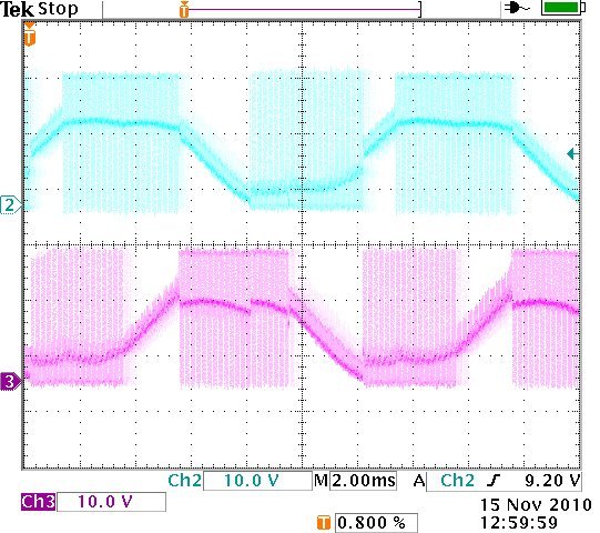
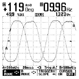
A sensorless brushless DC control consists of a power supply, a power stage, commutation logic, and startup logic. The key difference to an electronically commutated BLDC motor system is that the Hall sensor inputs are replaced by a system that measures generated voltage (BEMF = back EMF) and uses zero crossings to determine when to switch on (energize) the windings.
The screen shot on the right shows BEMF with hall sensor aligned to commutate a conventional BLDC (ECM) motor or gearmotor.
How does the sensorless BLDC control work?
The BLDC motor is started “open loop” by sequencing the power switches to start rotation. Usually this involves a fixed time interval based on inertia to accelerate the motor. Once the motor speed is high enough to “read” BEMF signals the commutation loop is closed allowing normal brushless motor operation.
What are the limitations of a sensorless BLDC system?
The initial BEMF detection is based on motor speed. Hence, the motor has to achieve a minimum speed for the BEMF sensing to work. In addition, BEMF sensing requires filtering to remove PWM noise. The filtering of the signals introduces delays in the measurements. All these limitations result in a speed range limitation that is normally between 5:1 and 10:1. Another issue that occurs with a sensorless BLDC motor and control system is that the motor shaft will likely move prior to starting up.
What are the benefits of a sensorless BLDC system?
This simplified motor-control connection scheme might reduce the risk of mis-wiring the motor and control system. In addition, one should see cost savings due to the elimination of hall sensors in the motor, and because less cables and connections are required. A sensorless BLDC motor will be a less complex assembly, the lack of an internal commutator might also allow for a slightly smaller motor size.
What is Back EMF?
Back EMF is the voltage produced across a winding of a motor due to the winding turns being cut by a magnetic field while the motor is operating. This voltage is directly proportional to rotor velocity and is opposite in polarity to the applied voltage (sometimes also referred to as counter EMF)
Back EMF definition from the Bodine Electric Small Motors Handbook – Glossary of Terms (p. G-2)
Gearmotors with Built-In 24VDC Brushless Control:
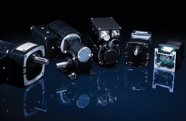
To minimize wiring and connection challenges with electronically commutated BLDC (ECM) motors and gearmotors, Bodine Electric offers a stock selection of INTEGRAmotors and gearmotors. Our INTEGRAmotors offer a cost competitive, all-in-one, easy to wire brushless DC drive solution for specialty machine builders and OEMs that don’t want to deal with high-cost and very complex stepper or servo systems. For more info, click here: INTEGRAmotor, a smart choice…
As always, we hope you find this information interesting. If you have comments or questions, please leave your comment here, or send an e-mail to: edmund.glueck@bodine-electric.com
Regards, Edmund [Manager, Marketing and Product Development/Standard Products]
Copyright Bodine Electric Company © 11/2010. All rights reserved.


