Installing a Terminal Box onto a Motor/Gearmotor (IP-44)
Example: Terminal Box model 0984. Mounting Instructions 07400067E.

The motor/gearmotor is factory-installed with a bushing on the lead exit. In order to install the terminal box onto the motor/gearmotor, this bushing must be removed. Unscrew and remove the plastic bushing from the motor/gearmotor’s center ring terminal opening and discard (except for type 34R motors/gearmotors. Leave the standard bushing in place).

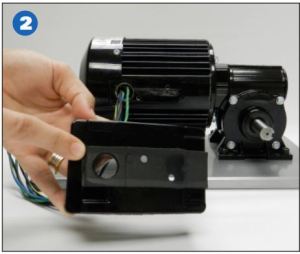
Adhere the foam gasket to the outside face of the terminal box with the precut gasket holes aligned with the terminal box holes. Then pull the terminal leads through the opening in the back of the terminal box.

Secure the terminal box to the motor/gearmotor’s center ring. Follow the instructions detailed in the Mounting Instructions for Bodine Type 34R, 42R, and 48R (AC) Motor and Gearmotor U.S.A./Canada Terminal Box Kit (literature no. 07400067E).

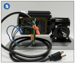
The capacitor for this gearmotor fits inside the terminal box, as do most of the standard stock capacitors for stock PSC motors/gearmotors. Install the run capacitor inside the terminal box. Mount larger capacitors externally.

Make all connections per the motor/gearmotor wiring diagram, adding a cord/capacitor/etc. as instructed by the manufacturer. Add a strain relief or PG fitting to the cord exit to meet IP-44 (not supplied with terminal box).

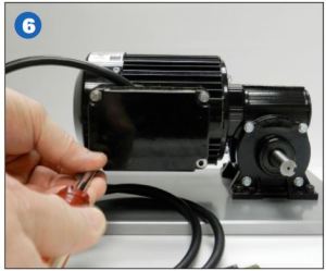
Follow the instructions detailed in literature no. 07400067E to fasten the terminal box cover and gasket onto the terminal box with the 4 screws provided.
To download this blog post as a PDF, please click here for literature item 07470039A.
Copyright Bodine Electric Company © 11/2018. All rights reserved.
