Motor constants are needed to calculate permanent magnet DC (PMDC) or brushless DC (BLDC or EC) motor specifications and ratings, or to match the motor properly to an amplifier. The motor constants are required in order to predict the PMDC or BLDC motor’s performance with changing variables, such as different input voltages or different loads. (See below PDF link for Bodine stock PMDC and BLDC motor constants.) This application note explains what the constants are, how they are derived and how to use them.

Common Motor Constants:
The most commonly used motor constants are Torque Constant (Kt), Voltage Constant (Ke), Electrical Time Constant (Te), Mechanical Time Constant (Tm), and Thermal Resistance (Rth). Typical values for these constants are derived by using measured values of No Load Speed, No Load Current, Stall Torque, Circuit Resistance, Circuit Inductance, and Armature Inertia with the following equations:
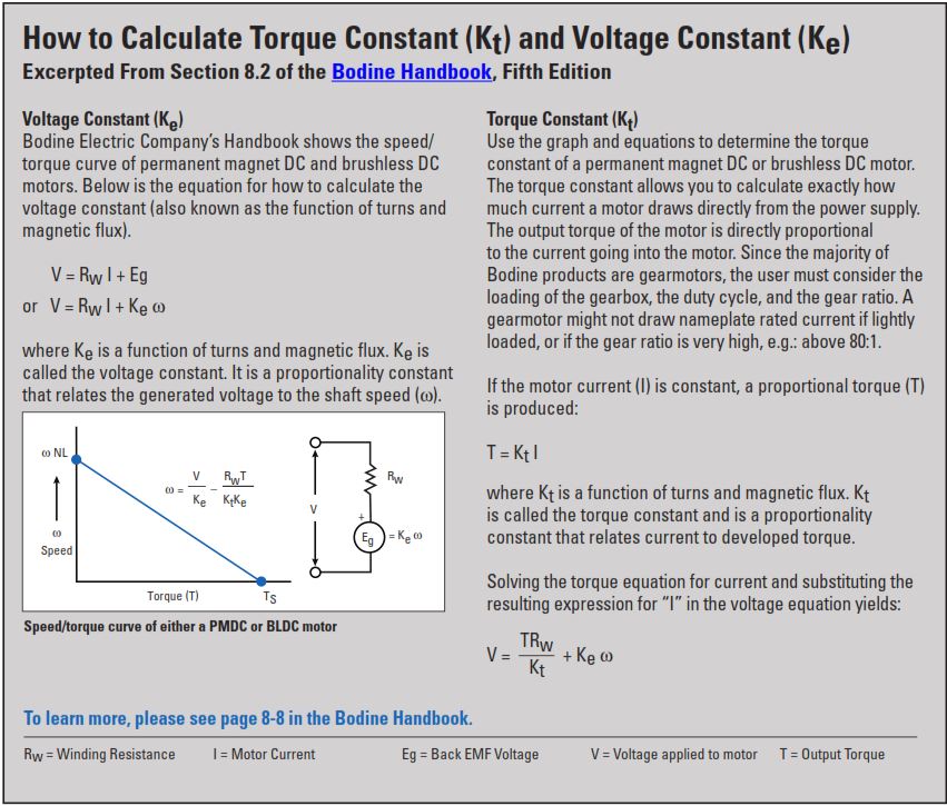
Torque Constant (Kt) — describes the proportional relationship between torque and current. Kt is usually expressed in the units Oz-in./Amp. See page 2 for additional information about torque constants.

Voltage Constant, or Back EMF Constant (Ke) — is the Torque Constant expressed in different units, usually Volts/Krpm, in order to describe the proportional relationship between motor speed and generated output voltage when the motor is back driven as a generator in units of Volts/1000 rpm. See page 2 for additional information about voltage constants.

Electrical Time Constant (Te) — is the time required for a motor to reach 63.2% of its stall current after applying a test voltage with the motor shaft locked. It is usually expressed in milliseconds. Applied Voltage equals Rated Current multiplied by Circuit Resistance:

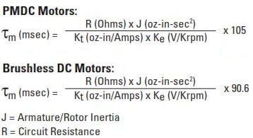
Mechanical Time Constant (Tm) — is the time required for an unloaded motor to reach 63.2% of its no load speed after applying its rated voltage. It is usually expressed in milliseconds.

Thermal Resistance (Rth) — is useful for predicting the ultimate temperature rise under different loading conditions in order to determine a maximum continuous torque rating. It is usually expressed in the units °C/Watt.

Using Performance Data to Calculate Kt and Ke
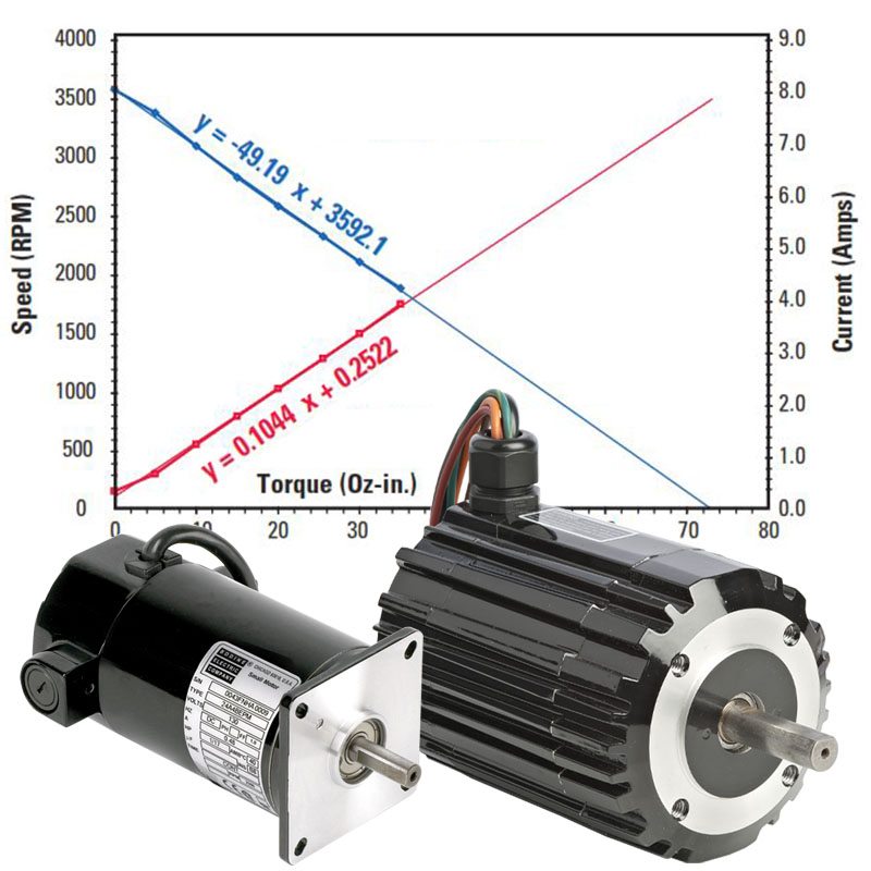
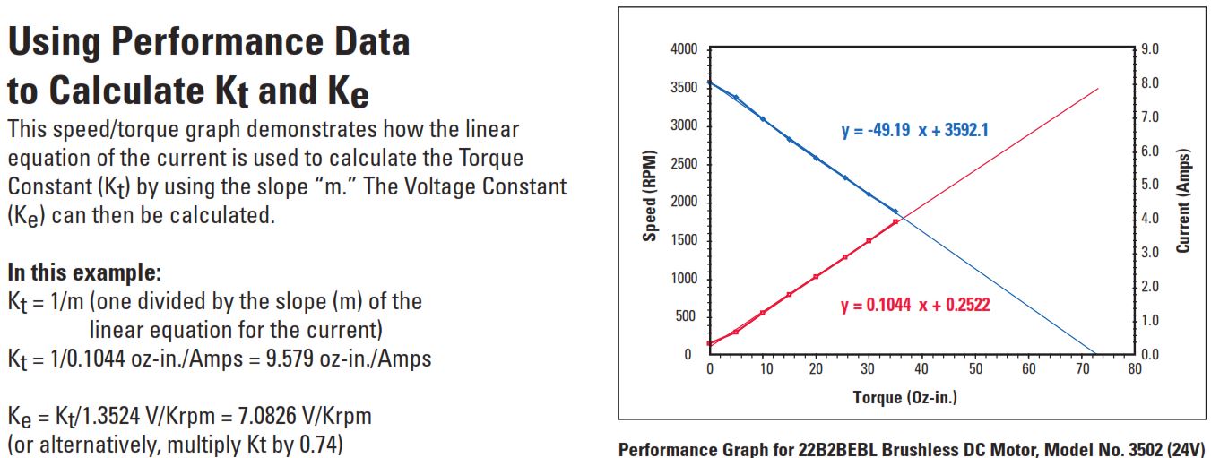
This speed/torque graph demonstrates how the linear equation of the current is used to calculate the Torque Constant (Kt) by using the slope “m.” The Voltage Constant (Ke) can then be calculated.
Using Performance Data to Calculate Kt and Ke
This speed/torque graph demonstrates how the linear equation of the current is used to calculate the Torque Constant (Kt) by using the slope “m.” The Voltage Constant (Ke) can then be calculated.
To download this information as a PDF, click here.
To download the Motor Constants for Standard Bodine Gearmotors, click here.
To download Chapter 8, or any other section of the Bodine Small Motors Handbook, click here.
Bonus Tech Tip: Another handy use for motor constants is when performing load measurements. If you are designing a machine and want to use an AC gearmotor, but you don’t know what size gearmotor you need. AC motors don’t have torque constants, but DC motors do. You might install a DC gearmotor into your prototype machine and use it as a “torque transducer”. By measuring the current draw, you can estimate what torque is needed when you start shopping for the AC gearmotor on Bodine Electric Company’s website
Copyright Bodine Electric Company © 11/2021. All rights reserved.

